|
|
|
|
|
|
|
| Windy Dankoff's Home Solar System - Part 1 | |
| by Windy Dankoff
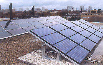
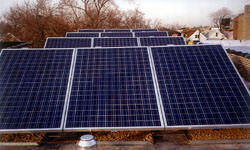
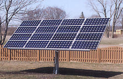
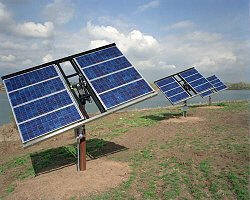
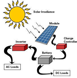
My wife and I found our perfect home in the woods, except for one thing -- it already had electricity from the grid. Half of the staff at Dankoff Solar lives with photovoltaic power, so the Dankoffs certainly should! We just installed a PV system to pump our water and to power some of the circuits in our house. It also gives me a way to test new products and ideas. I will describe the power and water supply systems now, so you can learn from my experience. In Part 2, I will describe the how I am tying power into the house, and reducing the lighting load. DESIGN GOALS. I wanted my system to pump all of our water, to supplement the house, and to keep some of our circuits going during power failures. I wanted a PV array that wouldn't cost a fortune or be visible from a mile away. Therefore, energy efficiency would be a priority. I also wanted a battery bank to carry us through a power failure of several winter days. SYSTEM LOCATION. I installed the PV array and power system near the water well, 140 feet from the house. Our wellhead is located at the bottom of a covered pit that also contains the pressure tank and water filters. The pit is 6 feet deep and 7 feet in diameter. It is made of galvanized steel culvert material. I called the well driller and had him install a similar pit to contain the power center, batteries and inverter. Many of our dealers have used this "power pit" concept. It gives protection from temperature extremes, it's unobtrusive, and it's cheap (as long as the location doesn't have a high water table). I also put in some shelves for storing food. The PV array is installed nearby, on a pole-top tracker. PV ARRAY AND TRACKER. To size the PV array, I did a load calculation for summer drought conditions, to supply 500 gallons per day. Working from the pump specifications, I determined the daily watt-hours to be about 1000. I chose our 85-watt, BP Solar BP-585 modules, because their extra quality and embedded-grid cell construction makes them more efficient, and thus more compact, than others (see "BP Solar Modules: Independent Lab Test"). I figured on a 9-hour peak solar day, assuming the use of a solar tracker during the driest summer weather. Calculation indicated that only two 85-watt modules would produce more than enough energy for water lift and pressurizing -- Surprising, isn't it? I decided to go with four of the BP modules. This will give us enough surplus energy to run my home office and some compact fluorescent and LED lights in the house. In case of a long power failure, the battery bank would have good capacity to run our Conserv refrigerator, our gas heating system, and the blower that distributes heat from our wood stove, for about four winter days. The solar tracker gives the array a 40% average energy gain during the warm half of the year, when we need the most water. I chose the Zomeworks Track Racktm because it is simple and cost-effective. The only moving parts are the rack axis, a shock absorber, and the refrigerant fluid that flows from one side to the other to tip the balance. I used the new "universal" tracker that accommodates various sizes and brands of PV module. It took about two extra hours to measure and place the parts to fit my modules, but it worked out fine. The tracker requires a 3" pipe for its pole but that is not strong enough to handle the extra height, so I had 5 feet of 3" pipe welded to a 4" pipe. After we did the assembly and wiring on the ground, a neighbor came over with his backhoe to lift the finished array onto the pole. It tracks beautifully, even on windy days. SYSTEM VOLTAGE DC voltage standards are 12, 24 and 48V. 24V is a happy medium and is most common for a system of this size. A 12V system would require four times the wire size in all DC circuits, and would necessitate wiring battery sets in parallel, which is not ideal (see Batteries: How to Keep Them Alive). A 48V system was not an option because 48V charge controllers and inverters are only available in sizes much larger than we need. CHARGE CONTROLLER I'm testing a new Solar Boosttm 50 charge controller with MAXIMUM POWER POINT TRACKING. I have observed over 20% gain in charge current, compared to a traditional controller. (See "Solar Boosttm MPPT Charge Controllers") STORAGE BATTERY I selected a battery bank of 970 amp-hours capacity. This is relatively large for the array and the load on the system. I wanted a large set because it allows future expansion and gives us a good reserve during power failures. I chose batteries of the conventional wet cell lead-acid variety, made by Surrette/Rollstm. They have a high reputation for quality and reliability. I expect these batteries to last for at least 15 years of our relatively light service. Lowering the batteries into the pit was easy. Rolls dual container batteries allow you to unbolt and remove individual 2V cells. It is then safe to suspend them by their terminals. We used a 4:1 rope and pulley system suspended from a step-ladder, to lower each of the 12, 95-pound cells down one at a time. WATER WELL PUMP AND STORAGE TANK I installed the most energy-efficient pumping system that I could, using two DC pumps and a storage tank. This system uses less than half of the energy (watt-hours per gallon) of a conventional AC pump powered by inverter (see Inverter Sizing for Submersible Pump Applications). By utilizing a storage tank, the well pump could be set to run only during daylight hours to eliminates some battery loss. The tank provides a safety buffer in case of pump failure. The additional cost of DC pumps and a storage tank is compensated by savings in the power system, which would have been doubled in size to run our original AC pump. The storage tank is made of drinking water-grade polyethylene, designed for burial. It stores 1200 gallons, which is sufficient for 4 to 8 day's supply, depending on the season. Our water well is 285 feet deep. It had a 230V, 1HP submersible pump. After I got the power system, storage tank and pressure pump working, I used the AC pump one last time to fill the tank before our well driller pulled it out. Discoloration on the drop pipe indicated our static water level to be around 125 feet, so I chose to set a SunRisetm Submersible pump at 150 feet. Five days later (still with a half-full tank of water) Paul and I lowered the SunRise pump by hand, using 3/4" flexible polyethylene pipe. WELL PUMP CONTROLS To power the SunRise pump, I decided to use our SC-1B battery system controller. The SC-1B contains a voltage converter, to let us run the pump at the full 60V from our 24V battery. That way we can pump any time we want, if necessary. It also has a variety of safety features and indicators (see SunRise Pump and Systems Specifications). It has a low voltage disconnect (LVD) with two modes of operation. Mode 1 is normal LVD, set to shut off below 22V to prevent malfunction or battery damage. Mode 2 raises the shut-off to 25V so that the pump only runs when the battery is receiving a charge. I selected mode 2 so that the pump does not draw from the battery at night. When the float switch in the storage tank calls for water at midnight or on a cloudy day, the controller waits until the battery is receiving a good charge. This eliminates battery loss. Normally we can wait a few days for the voltage to rise because our tank stores plenty of water. The storage tank has two float switches in it. One is near the top. It turns the pump on when the tank is about 90% full, and off when it's full. I added a manual override switch to allow the tank to overflow when desired. An overflow pipe leads to a low spot on our land where we will plant some trees. When there is excess energy during dry summer weather, it will support a beautiful little forest. The second float switch is located low in the tank. If the tank gets down to the last 20%, a this switch causes the LVD in the controller to set to mode 1 to run the pump even if the battery voltage is not high. This is easy to do because the LVD mode 2 is selected by adding a jumper wire between two terminals. Simply wire a float switch to the terminals, instead of the jumper (a switch that makes contact on rise). PRESSURIZING SYSTEM Our storage tank could not be located higher than the house, so we use a pressurizing pump to deliver the water. Our Flowlighttm Booster Pump has sufficient capacity for our indoor water use, but we have some irrigation demand that can exceed its capacity. So, I picked our 24V Solar Forcetm Piston Pump. I'm very fond of the Solar Force. It's a heavy, quiet slow-speed pump that is good for decades of service, and it's extremely energy-efficient. The DC motor eliminates yet another load on the inverter. It supplies 60 PSI to our 85 gallon pressure tank that remains from the original AC system. BATTERY MONITORING -- THE TRI-METRIC I consider it extremely important for system users to have easy indicators of critical quantities, especially the battery state-of-charge (SOC) and water level in the storage tank. I want these to be easy to read not only for my wife and I, but for any future housesitter or renter. For the power system, I chose the Tri-Metrictm TM-2020 battery system monitor. Its display of "% Battery Full" is as easy to understand as a car's fuel gauge. The Tri-Metric accomplishes this by counting amp-hours flowing to and from the battery. (A mere voltage reading cannot give battery SOC without the user also knowing the current flow, and understanding basic battery dynamics.) The advanced user or technician can access additional data to facilitate battery maintenance, energy management and troubleshooting. At a list price of $185 (with shunt) this meter belongs in all but the least expensive battery-based renewable energy systems. It can be placed remotely, even hundreds of feet away. I installed my Tri-Metric on a tree near the power pit, in a weatherproof box with a glass window. WATER TANK MONITORING I also wanted an easy way to read the water level in our buried storage tank. In the adjacent well pit, I rigged a sight tube. It looks like a big thermometer with %-full marks. I tapped a small fitting into the pipe that feeds the pressure pump, and connected a piece of 3/4" clear vinyl tubing that extends upward just higher than the top of the tank. I made a little plastic float to go inside the tubing, to make the water level more visible. You can see it when you lift the access lid of the pit.
|
|
Home Forums SMARTMAIL Calendar eCards Help Hot!! NSW/ACT QLD SA TAS VIC WA NT
Copyright © 2025 www.envirorealestate.org.au
'Australia's free environment friendly real estate service for agents and owners'
~ All rights reserved. Revised:
July 03, 2010 ~